英语
英语 日语
日语 中文简体
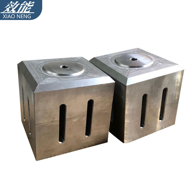
中文简体Design method of ultrasonic tooling and ultrasonic welding line
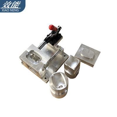
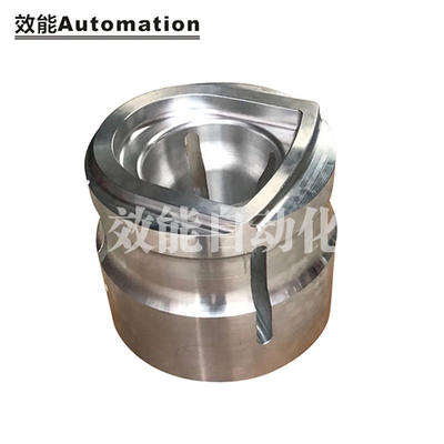
Ultrasonic Plastic Welding machine will leave scars on the surface of ultrasonic plastic parts during ultrasonic welding when there are damage lines on the surface of the tooling, or its shape is more or less different from the ultrasonic plastic parts. The way to avoid it is to put a film between the ultrasonic tooling and the surface of the ultrasonic plastic part.
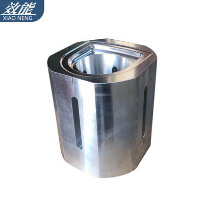
The contact surface of the ultrasonic plastic part should be at least larger than the ultrasonic welding surface, and the ultrasonic welding position should be aligned as far as possible. Too small contact surface of ultrasonic welding head will cause greater damage and deformation, as well as unsatisfactory ultrasonic welding effect.
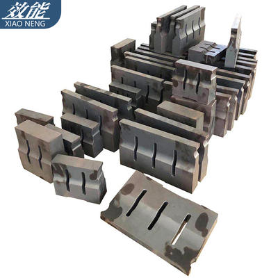
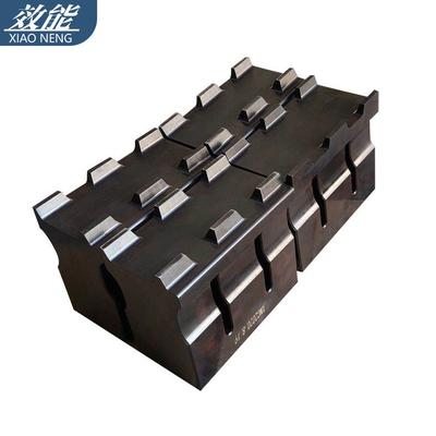
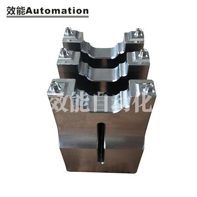
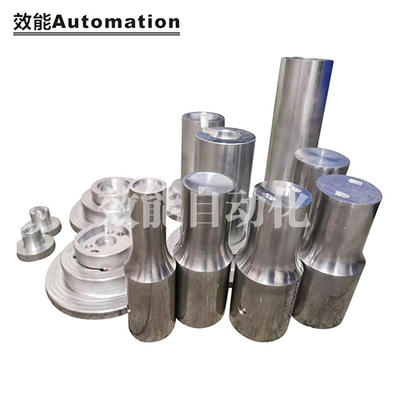
Injection parts can be designed into any shape, but ultrasonic tooling cannot be made arbitrarily. The shape and length may affect parameters such as the frequency and amplitude of the ultrasonic horn. The design of ultrasonic tooling needs to have a reference plane, that is, the reference frequency plane determined according to the frequency of its workpiece. The reference frequency plane generally occupies more than 70% of the surface of the welding head, so the shape of the protrusions on the surface of the injection molded part is preferably smaller than the entire plastic and then 30%. For smooth, arc-transitioned surfaces of plastic parts, this standard can be appropriately relaxed. And the protruding position should be located in the middle of the ultrasonic plastic part as much as possible or symmetrically designed.
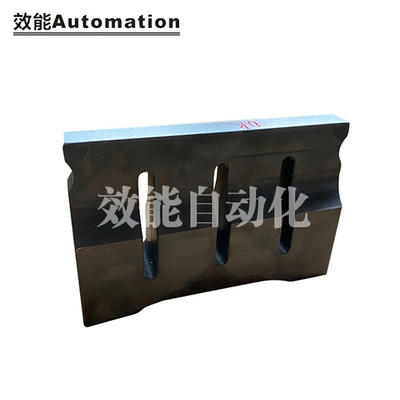
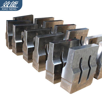
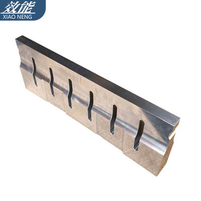
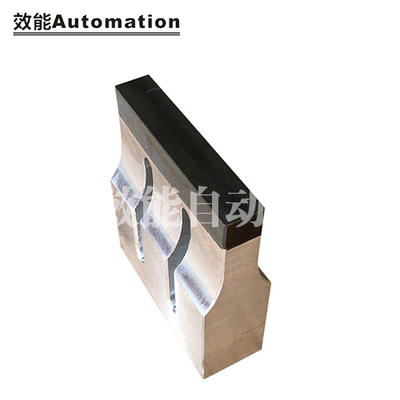
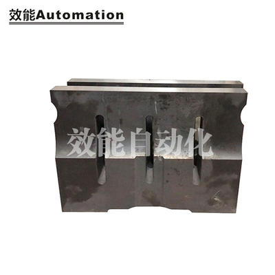
The welding line is the part that is melted by the direct action of ultrasonic waves, and its basic two design methods:
①Cut design
② energy orientation
All other variations can be classified into either type or a hybrid type.